PLC Status Screen
The Expanded Status screen is the single best place to check what the system is doing right now. Press F1 from the home screen — no password required.
|
PLC navigation at a glance
|
Reading the Status screen
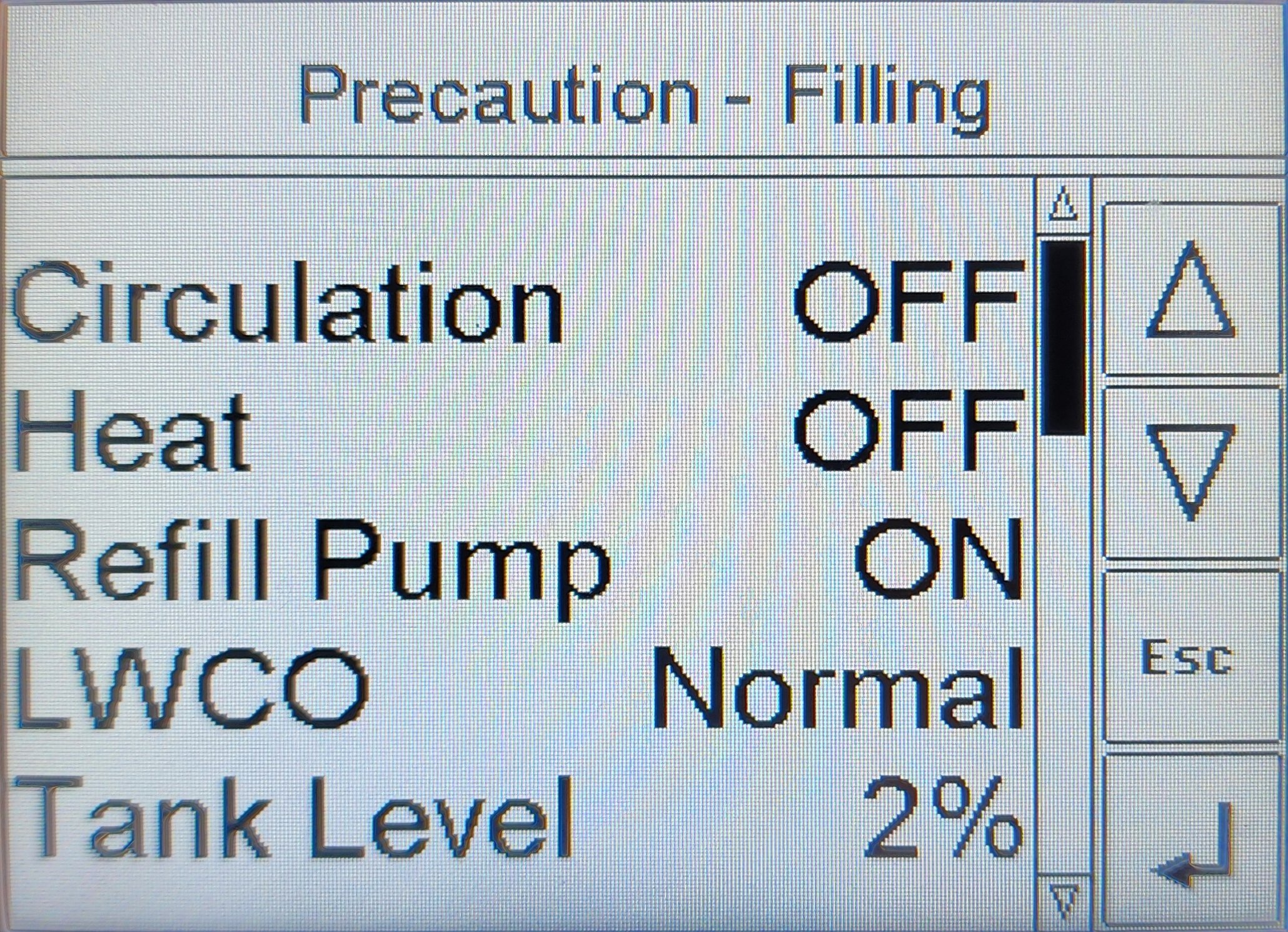
Precaution - Filling condition — circulation and heat are paused while the refill pump tops up the tank. The screenshot shows the first five lines of the scrollable list.The Status screen is a scrollable list. Use the on-screen ▲ / ▼ arrows to scroll. The banner at the top of the screen is the current system state — the same banner shown on the Home screen.
The full list of fields, in scroll order, is:
| Field | Format | Meaning |
|---|---|---|
Circulation |
Text |
|
Heat |
Text |
|
Refill Pump |
Text |
|
LWCO |
Text |
|
Tank Level |
Numeric, % |
Tank coolant level as a calibrated percentage. Refill is automatic; with the supply drum kept full there is no need to monitor this value. Calibrated via Tank Level Calibration. |
Tank Temp |
Numeric, °F |
Tank coolant temperature, read from the dedicated PLC tank-temp probe. |
Refill Timer |
Numeric, seconds |
Elapsed seconds in the current refill cycle. Counts up against the Fill Time Limit. |
Refill Pres. |
Numeric, PSI |
Live refill-line pressure. |
Ambient |
Numeric, °C |
Cabinet ambient temperature. Drives the cooling-fan and LCD-heater logic. |
Fan |
Text |
|
LCD |
Numeric, °C |
Temperature at the HMI screen itself. |
LCD Heater |
Text |
|
Aux Pump |
Text |
Master enable for the auxiliary circulation pump ( |
Aux Setpoint |
Numeric, °F |
Tank-temperature threshold at which the aux pump enables. |
Aux Pump |
Text |
|
Version |
ASCII |
Firmware version (currently |
|
Temperatures are shown in two units
The PLC displays Tank Temp and Aux Setpoint in °F, and Ambient and LCD in °C. This is how the controller is programmed. The cooling-fan and LCD-heater setpoints on the Controls screens are also in °C. Where this manual quotes a factory default, it gives both units — see Specifications — Enclosure temperature regulation. |
|
Two rows labelled Aux Pump
Two adjacent fields share the Aux Pump label on the screen — one is the master enable ( The aux pump itself is a special-order option — a 3rd circulating pump driving a separate heating loop. Most units do not have it. If yours does not, these three rows are still shown on the screen but represent no physical pump. See Aux Circulation Pump. |
System states
The banner at the top of the Home and Status screens reports the current system state as a literal text string. The same string is recorded in the unit’s event log on every state transition.
The full list of state strings the PLC reports — in order of progression through a normal session — is shown below. State strings are reproduced verbatim, including their (intentional) spacing.
| State | Meaning |
|---|---|
|
Logged once at controller boot. Not a persistent state. |
|
System is in standby, awaiting Start. No outputs energized. |
|
Momentary marker logged at the instant the operator presses Start. Immediately superseded by |
|
System enabled and ramping toward operating temperature. Indicator slow-blinks. |
|
Normal operating state — circulation running and boiler enabled at temperature. Indicator solid. |
|
Normal operation, plus the refill pump is topping up the storage tank. |
|
Momentary marker logged at the instant the operator presses Stop. |
|
Boiler disabled, circulation pump still running through its off-delay. |
|
The operator E-Stop button is depressed. System locked out; strobe latched. |
|
The Low-Water Cut-Off has tripped. System locked out; strobe latched. Replenish coolant before resetting. |
|
Brief hold after pressing Reset while clear-conditions are evaluated. Returns to |
|
System is refilling the storage tank (initial fill or post-drawdown). |
|
Refill pressure exceeded the configured maximum — refill stopped, fault latched. |
|
Refill ran longer than the configured fill time limit — fault latched. |
|
Momentary marker logged at the instant the operator presses Reset. |
|
The external refill switch is off — heating is not enabled and the refill pump is locked out. |
|
Tank fell to a near-empty level (below ~3 %) without LWCO tripping. Circulation and heat are paused while the refill pump catches up. Returns to |
|
Why "Precaution" exists
The |
|
Event logging
Every state transition is recorded as an event in the unit’s data log, and the current state is also logged at periodic intervals as a heartbeat. The log is the authoritative record of what the unit was doing at any past moment — useful for diagnosing intermittent issues after the fact. To retrieve the log, see PLC Data Log. |