PLC Controls and Setpoints
The Controls menu holds the adjustable setpoints and time limits that are not part of a calibration routine: the cooling-fan and LCD-screen-heater setpoints, the fill time limit, and the auxiliary circulation pump setpoint. The fill time limit is part of the refill protection logic — read its section before changing it.
Where each screen is
The Controls screens are a chain. Press F2 from the home screen, enter the password, and select Controls: the first screen opens. Use the next and previous arrows on each screen to move along the chain.
| Screen | How to reach it |
|---|---|
Menu → Controls |
|
Menu → Controls → next |
|
Menu → Controls → next twice |
|
Menu → Calibration → Tank → next twice (after TANK LOW % CAL and TANK High % CAL) |
|
PLC navigation at a glance
|
Cooling fan
The PLC switches the cabinet cooling fan from the cabinet ambient temperature probe. The fan turns on when ambient temperature reaches the High setpoint and stays on until it falls to the Low setpoint. The gap between the two setpoints keeps the fan from switching on and off rapidly around a single temperature.
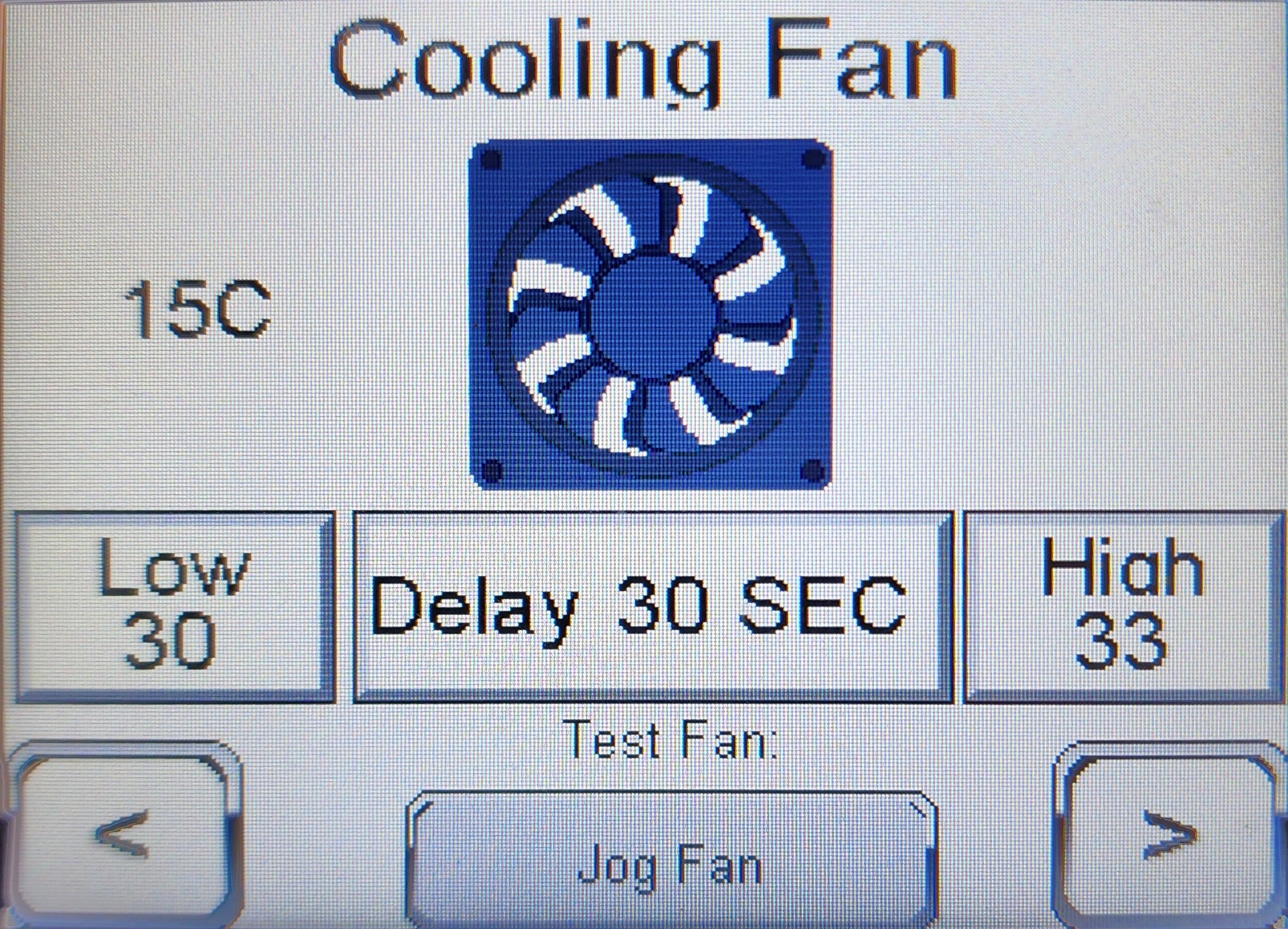
| Field | Meaning |
|---|---|
Low |
Ambient temperature (°C) at or below which the fan turns off. Default 30 °C (86 °F). |
High |
Ambient temperature (°C) at or above which the fan turns on. Default 33 °C (91 °F). |
Delay |
Minimum delay between state changes (default 30 s) — prevents short-cycling near the setpoint. |
Jog Fan |
Manual fan run for verification — energizes the fan output for a brief test. Use during commissioning or after maintenance. |
LCD screen heater
|
Deprecated
The LCD screen heater is deprecated. Current units are built without it. On a unit without the heater, the LCD Screen Heat screen and the LCD Heater line on the Status screen are still shown but have no effect. |
The HMI display is heated in cold weather to keep the LCD readable and within its operating temperature. The PLC switches the heater from the temperature sensor at the HMI screen: the heater turns on at the Low setpoint and off at the High setpoint, with a delay between state changes.
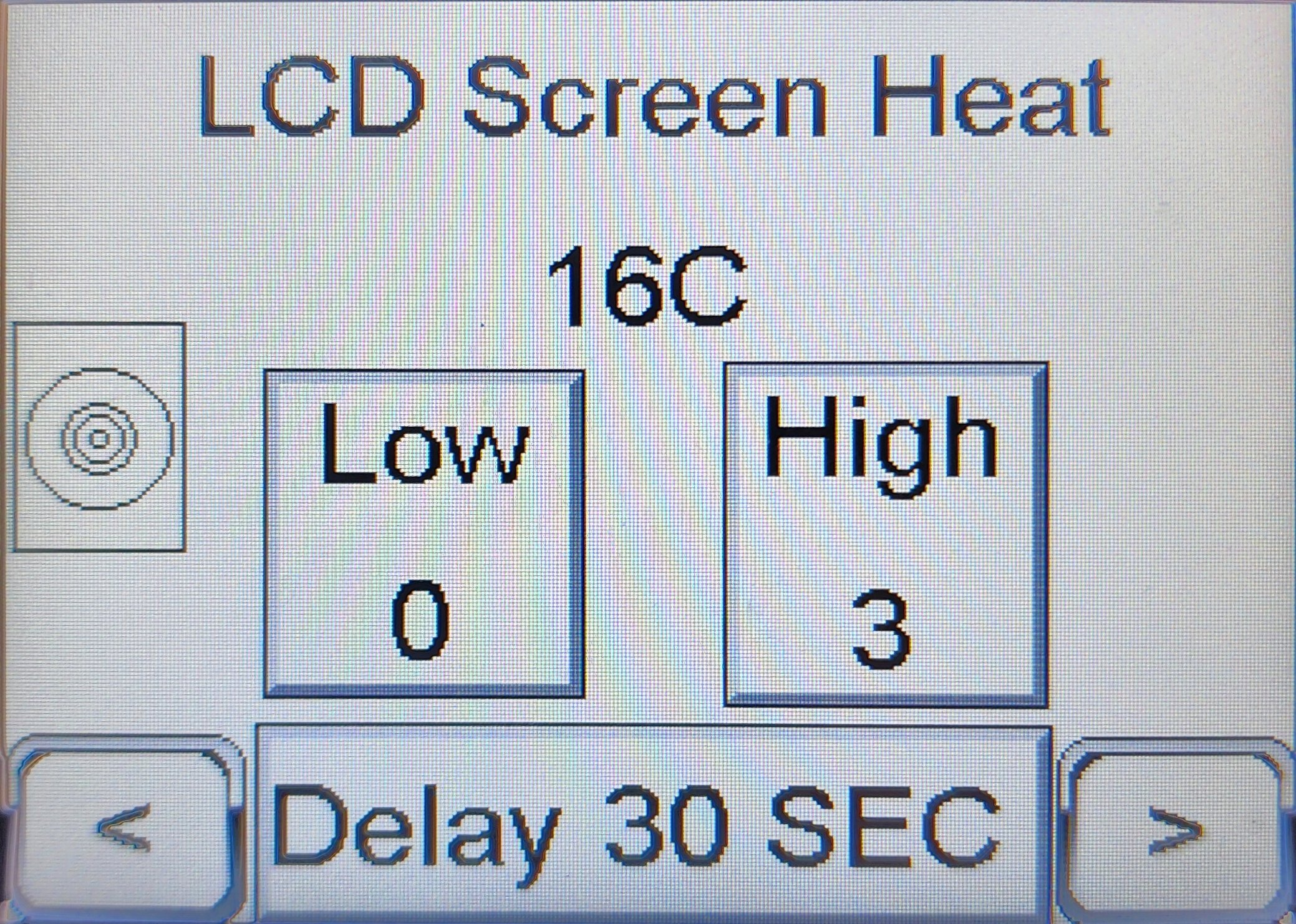
| Field | Meaning |
|---|---|
Low |
LCD temperature (°C) at or below which the heater is on. Default 0 °C (32 °F). |
High |
LCD temperature (°C) at or above which the heater is off. Default 3 °C (37 °F). |
Delay |
Minimum delay between state changes (default 30 s). The PLC accepts up to 60 s. |
Fill time limit
The fill time limit caps how long the refill pump may run continuously before the PLC declares a REFILL TIMER EXPIRED fault, latches the strobe, and locks out the system. This protects the unit from running the refill pump indefinitely on an empty supply drum, a kinked suction line, a stuck float, or a leak.
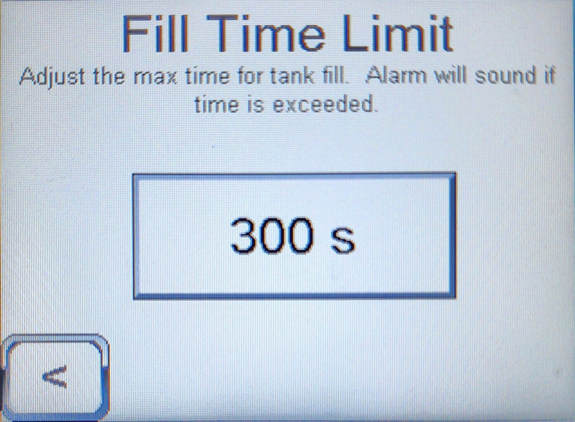
| Field | Default | Meaning |
|---|---|---|
Time limit |
300 s (5 minutes). The PLC accepts 60–500 s. |
Maximum continuous refill-pump run time. If exceeded, the PLC stops the refill pump, energizes the strobe, and locks out the system. |
|
Do not raise the fill time limit to work around recurring timeouts
A longer limit lets the gear-type positive-displacement refill pump run dry for longer before the fault trips, and it hides whatever is slowing the refill. The pump’s dry-running tolerance is approximately 20 minutes cumulative before pump damage. Do not raise the limit close to or above that threshold. If refill cycles are regularly approaching the 300 s limit, check for:
|
If the fill time limit trips
The PLC banner reads REFILL TIMER EXPIRED. Correct the cause, press Reset, wait for the banner to settle at OFF- Ready, and press Start. Step-by-step instructions are in Troubleshooting — Resolution — REFILL TIMER EXPIRED.
Auxiliary circulation pump
|
Deprecated
The auxiliary circulation pump is deprecated. It is not supported in later PLC software, which removes this screen and the pump output. Do not plan new installations around it. |
The auxiliary circulation pump is an optional third circulating pump that drives a separate heating loop. It is a special-order configuration for units that need to feed a second downstream load, and most TankerTherm 123 units are built without it. The Aux Circulation Pump screen is present on every PLC; on a unit without the pump, its settings have no physical effect.
The PLC runs the aux pump only when all three of these conditions are true:
-
Enable is on.
-
The system is enabled — a heating session has been started with Start and has not been stopped or locked out.
-
Tank temperature is at or above the Setpoint.
The pump stops as soon as tank temperature falls below the setpoint, so it runs only when the tank is hot enough to be useful for the secondary loop.
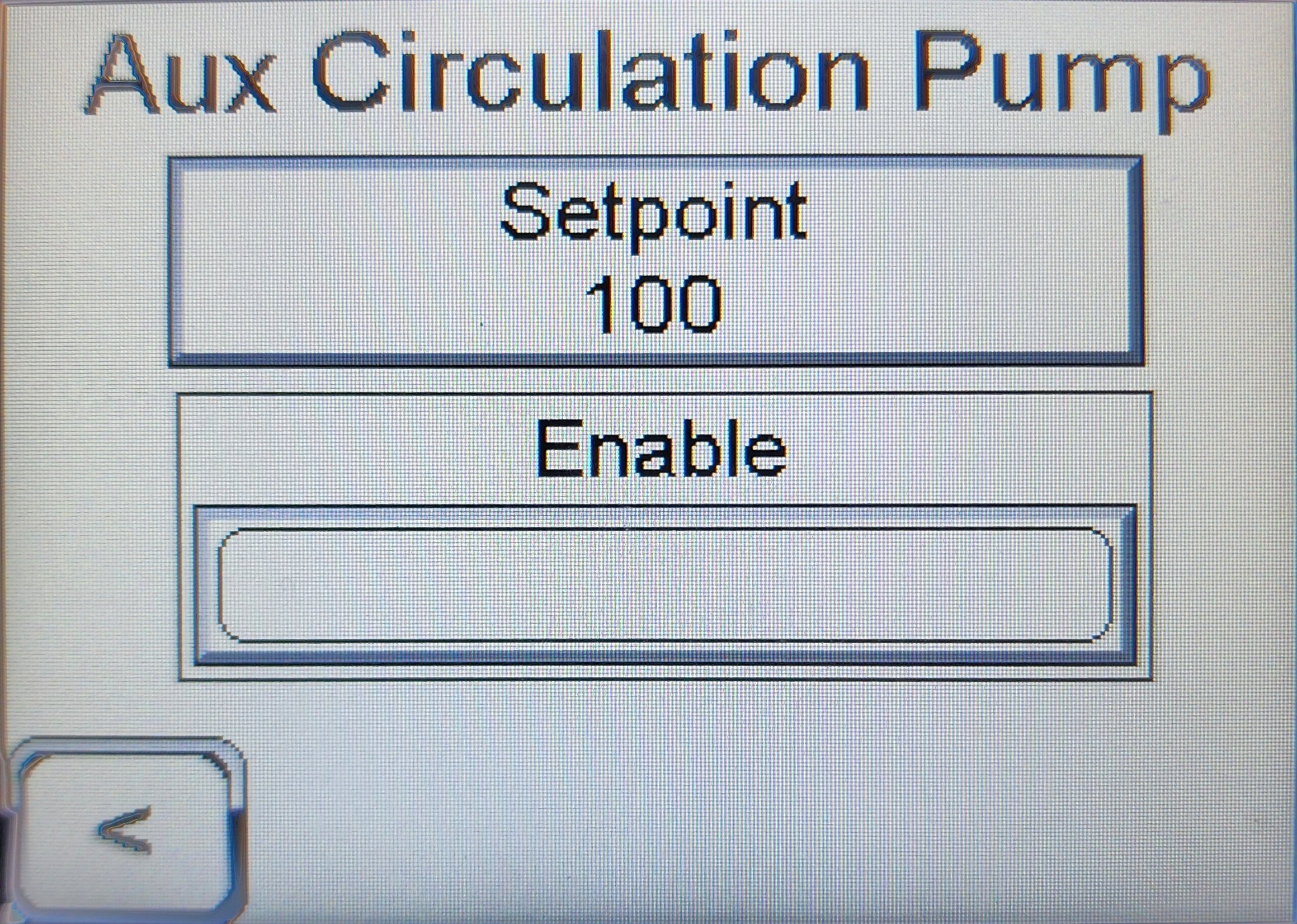
| Field | Meaning |
|---|---|
Setpoint |
Tank temperature, in °F, at or above which the aux pump runs. Default 100 °F. |
Enable |
Toggle button that turns the aux pump output on or off. When Enable is off, the aux pump does not run regardless of tank temperature. |
See also
-
PLC Controller Overview — strobe and indicator legend
-
Refill Pressure Calibration — companion protection