PLC Output Tests
The Output menu lets a service technician test the PLC’s discrete and analog outputs without putting the system into an operational state. Use these tests during commissioning, after wiring changes, or when verifying field-side equipment such as the strobe, the indicator lamp, or a connected SCADA / data-acquisition input.
|
PLC navigation at a glance
|
|
System should be at standby for output tests
The output tests drive the physical outputs directly, bypassing normal control logic. Stop the system before testing, or be prepared for the unexpected behavior of energizing an output during operation. |
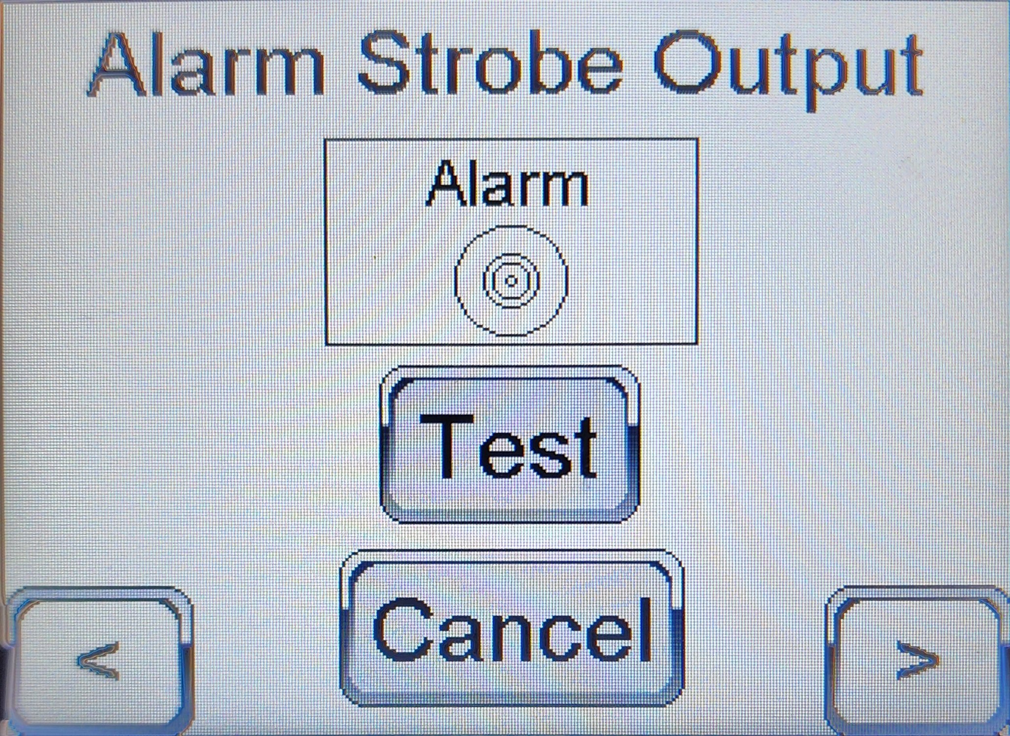
Alarm Strobe Output
Drives the strobe output to verify wiring, the strobe itself, and the cable run from the PLC to the manifold control panel.
-
Press F2 from the home screen, enter the password, and select Output → Alarm Strobe.
-
Press Test. The strobe energizes for the duration the screen is held active.
-
Press Cancel to drop the output.
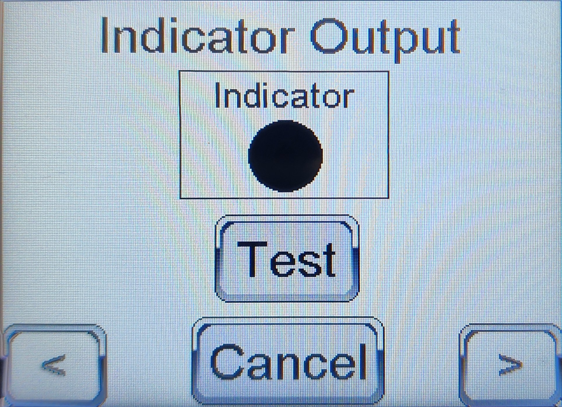
Indicator Output
Drives the indicator lamp output. Use to verify the lamp itself, the cable, or the placard alignment after panel work.
-
Press F2 from the home screen, enter the password, and select Output → Indicator.
-
Press Test. The indicator energizes for the duration the screen is held active.
-
Press Cancel to drop the output.
Temperature Analog Output
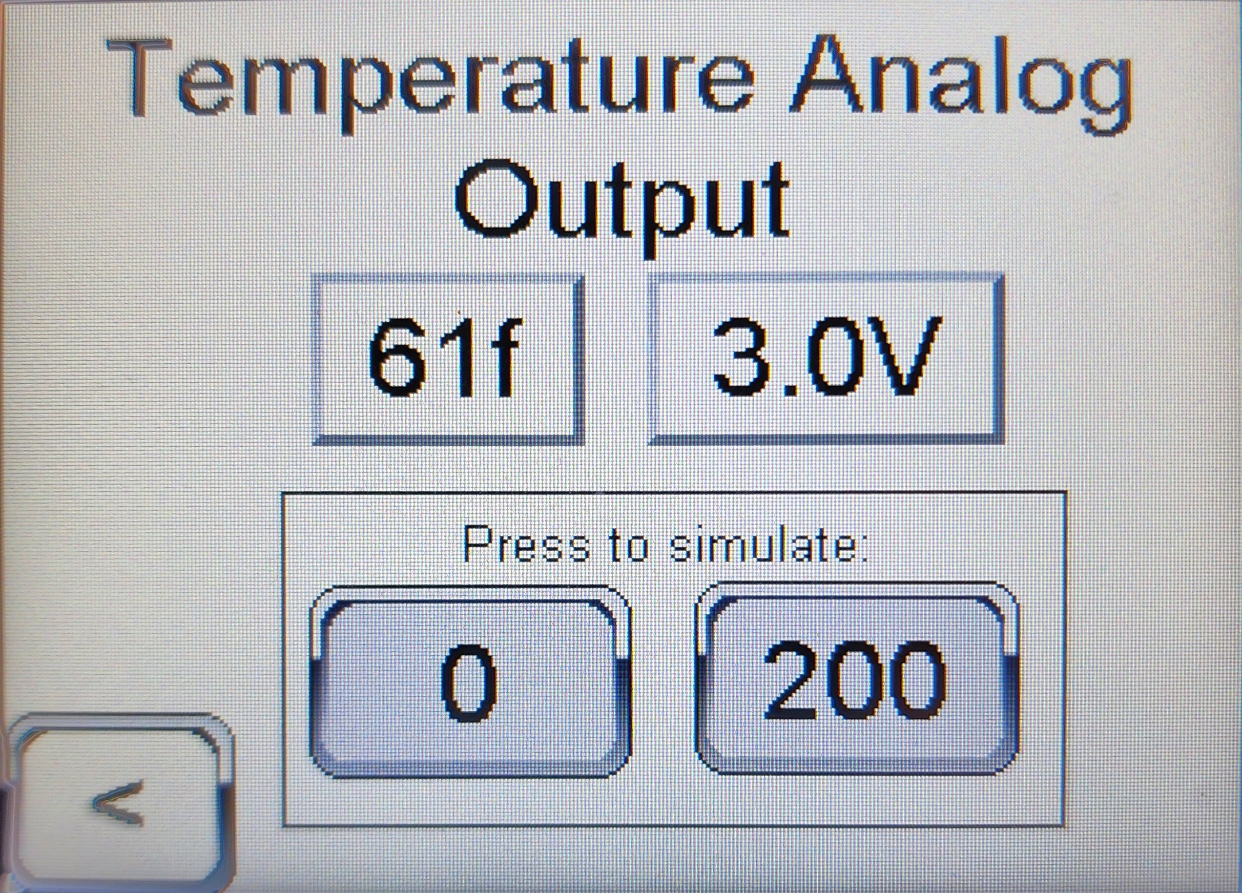
The PLC provides an analog output that mirrors tank temperature for connection to a remote monitoring or data-acquisition system. Output range is 0–10 V representing 0–200 °F.
| Element | Meaning |
|---|---|
Top reading (°F) |
Current tank temperature in degrees Fahrenheit. |
Top reading (V) |
Current analog output voltage corresponding to that temperature. |
|
Drives the analog output to 0 V (= 0 °F) for verification on the receiving side. |
|
Drives the analog output to 10 V (= 200 °F) for verification on the receiving side. |
|
Two-point loop verification
With a SCADA / DAQ system on the receiving end, press 0 and confirm the receiver reports near 0 °F (or 0 V), then press 200 and confirm the receiver reports near 200 °F (or 10 V). This proves the analog loop end-to-end without changing tank conditions. |
|
Simulation drives the live output
Pressing 0 or 200 drives the actual analog output. Any monitoring system or alarm tied to that signal will see the simulated value. Coordinate with whoever is watching the data feed before simulating. |
See also
-
Calibration procedures — for verifying probe inputs
-
Remote Output Box — physical termination of the strobe, indicator, and temperature outputs