Remote Output Box
The Remote Output Box is a terminal enclosure on the rear of the unit. It gives a customer-supplied monitoring system — such as a remote PLC, scoreboard, or SCADA / data-acquisition system — fused access to three status signals from the TankerTherm 123.
Every unit ships with the Remote Output Box. Wiring it is optional; the unit operates fully without it. It is the supported connection point for any third-party monitoring or annunciation.
Location
The Remote Output Box is a 4 × 4 enclosure mounted on the rear of the unit, adjacent to the high-voltage input. Cable entry is sized for typical low-voltage signal cable.
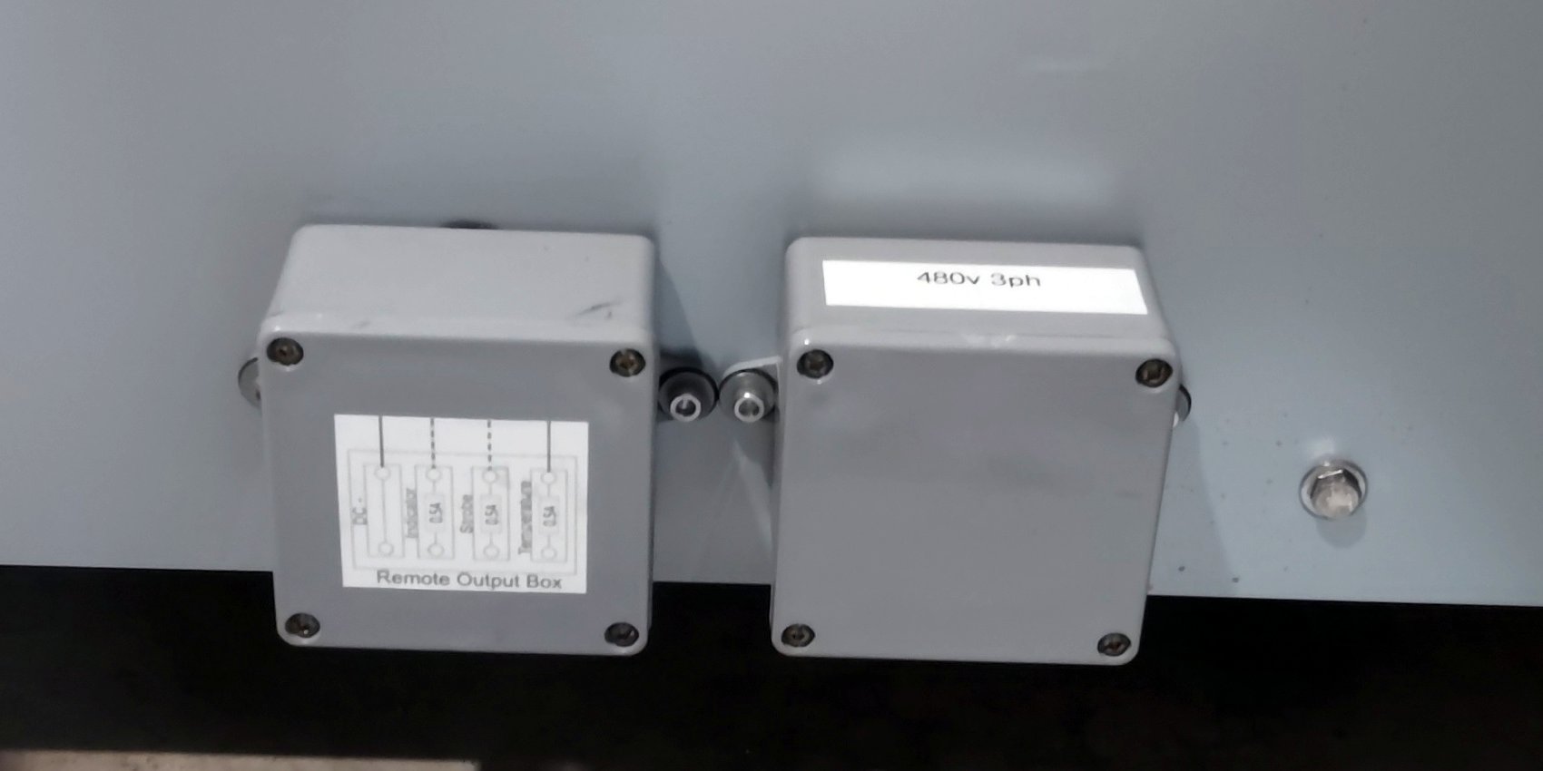
Control voltage
Outputs are driven at 12 V DC, supplied by an internal 3-phase-to-12 V DC converter that runs from the unit’s main 480 V or 600 V supply. The DC - terminal is the 12 V DC return common for all three outputs.
Available signals
-
Indicator — digital 12 V DC output that mirrors the manifold-panel indicator lamp, reproducing all blink patterns
-
Strobe — digital 12 V DC output that mirrors the manifold-panel alarm strobe (high when illuminated)
-
Temperature — 0–10 V analog output of tank coolant temperature, scaled 0–200 °F
Terminal layout
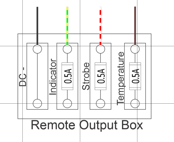
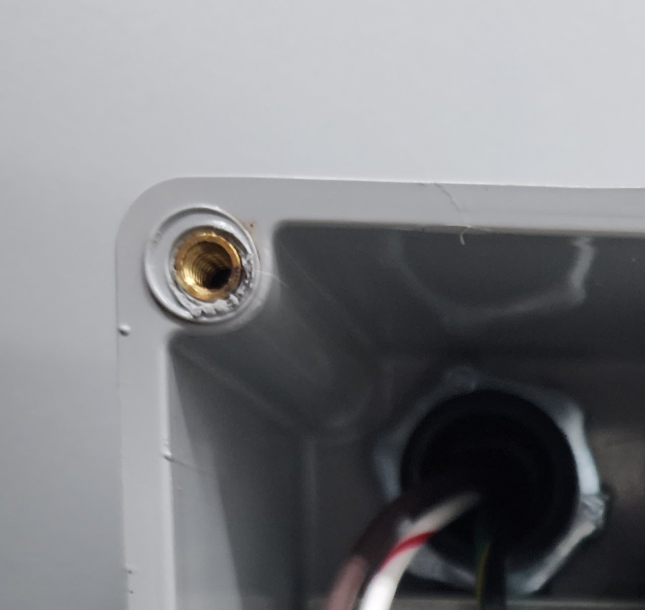
DC -; the three black fused terminals are, from left to right, Indicator, Strobe and Temperature. The factory wiring enters at the top of each terminal; the openings at the bottom take the field wiring.| Terminal | Fuse | Factory wire colour | Signal |
|---|---|---|---|
|
— |
Black |
12 V DC return / common for all three outputs |
|
0.5 A |
Green / yellow |
Digital 12 V DC mirroring the indicator lamp (with blink patterns) |
|
0.5 A |
White / red stripe |
Digital 12 V DC mirroring the alarm strobe (high when illuminated) |
|
0.5 A |
Brown |
0–10 V analog, scaled 0–200 °F |
|
Qualified electrician required
All electrical connections must be performed by a licensed electrician in compliance with local electrical codes. Disconnect and lock out the power source before beginning any electrical work. |
|
Replace fuses only with the same rating
Each output is protected at 0.5 A. Do not substitute a higher-rated fuse — the fuses protect the PLC’s output drivers and the 12 V DC converter as well as the downstream field wiring. |
Connecting loads to the Indicator and Strobe outputs
Treat the Indicator and Strobe outputs as signal outputs. Each is fused at 0.5 A; the fuse protects the circuit and is not a load rating to design to. Connect them directly to a PLC digital input, a scoreboard input, or a small 12 V DC indicator lamp. To switch a heavier load — a horn, a beacon, or a contactor coil — drive an interposing relay from the output and switch the load through the relay’s contacts.
Indicator output
The Indicator output reproduces the same blink patterns described in Indicator lamp:
-
Solid — heating
-
1-second steady blink — warmup / cooldown
-
Fast blink — resetting / initialization
-
Double blink & pause — tank low (Precaution mode); auto-resumes when full
-
Single blink & pause — refill system disabled
A remote lamp on the receiving side reproduces these patterns directly. A PLC on the receiving side can decode them using a pulse counter or duty-cycle measurement; reference the patterns above to map blink-codes back to system states.
Strobe output
The Strobe output is a digital signal — high when the local strobe is illuminated, low otherwise. It triggers on the same four conditions printed on the panel label (see Alarm strobe):
-
Refill Timer Expired
-
Refill Pressure Exceeded
-
Tank Critically Low (LWCO)
-
Operator E-STOP Pressed
A receiving system that reads this signal as an alarm input will see it fire on any of the four conditions; if the receiver needs to distinguish between them, it must also read the Indicator output (or query the PLC banner directly via a separate channel).
Temperature output
The Temperature output is the same 0–10 V analog signal tested by PLC Output Tests — Temperature Analog Output.
It is a voltage signal, not a 4–20 mA current loop. Connect it to a voltage-mode (0–10 V) analog input, which is high-impedance. Do not use it to power a device.
The mapping is linear:
| Output voltage | Tank temperature |
|---|---|
0 V |
0 °F |
10 V |
200 °F |
Each volt represents 20 °F: tank temperature (°F) = output voltage × 20. A 5 V reading therefore indicates 100 °F.
Verification after wiring
Confirm each output reaches the receiving end before relying on the connection.
-
Stop the system at the manifold panel.
-
From the PLC HMI, press F2, enter the password, and select Output.
-
Run each test in turn:
-
Alarm Strobe Output — press Test; confirm the receiving alarm input asserts. Press Cancel.
-
Indicator Output — press Test; confirm the receiving lamp or input asserts. Press Cancel.
-
Temperature Analog Output — press Press to simulate: 0; confirm the receiving channel reads near 0 V / 0 °F. Press Press to simulate: 200; confirm the receiving channel reads near 10 V / 200 °F.
-
-
Return the unit to service.
|
Simulation drives the live output
The simulation buttons drive the actual analog output. Any monitoring system or alarm tied to that signal will see the simulated value during the test. Coordinate with whoever is watching the data feed before simulating. |
See also
-
PLC Controller Overview — full indicator and strobe legend
-
PLC Output Tests — on-screen verification of each output
-
Power Supply Connections — high-voltage hookup