Startup & First Heat Cycle
The first heat cycle requires a mandatory air-purge step to prevent boiler damage. Read this page completely before attempting first startup.
|
Air purge is mandatory for first startup
Skipping the air-purge step will cause the boiler to activate while air is still in the system, potentially damaging the boiler. This damage is not covered under warranty. |
|
High voltage at the boiler face — lock out before touching any wire
Before touching any wire at the boiler face: open the upstream main disconnect, lock it out and tag it out, and verify zero voltage with a properly rated meter. This work must be performed by a qualified electrician. The boiler face exposes the 480 V or 600 V 3-phase supply next to the low-voltage control wiring. Contact with energized 3-phase conductors can be fatal. |
Step 1 — De-energize the unit and disconnect the control wire
-
Open the upstream main disconnect.
-
Verify zero voltage at the boiler with a properly rated meter.
-
Lock out and tag out the disconnect per site procedure.
-
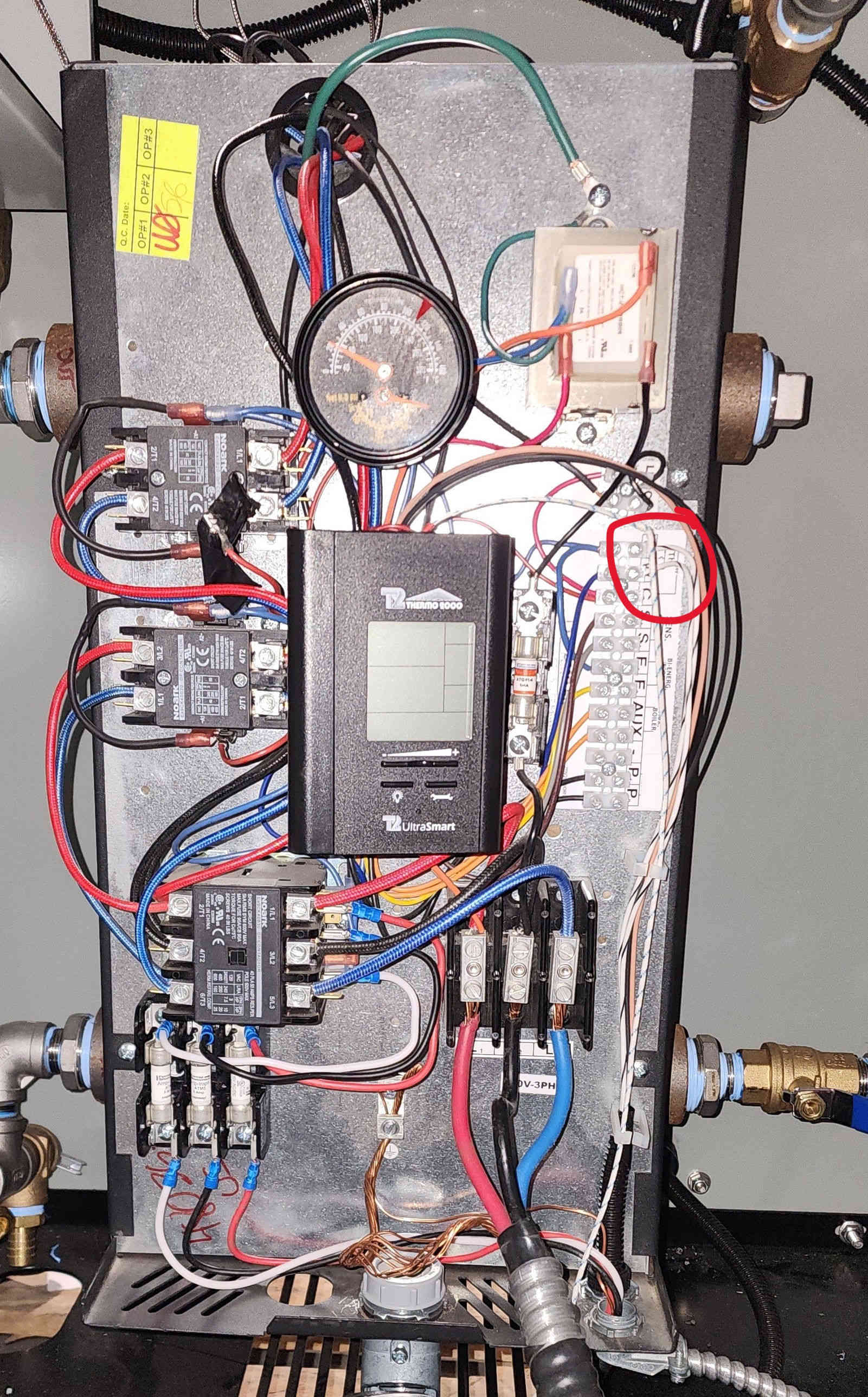
Disconnect the white/black control wire from boiler terminal
R. This disables boiler heating during the air purge.
Step 2 — Re-energize and run the air purge
-
Remove lockout/tagout and close the main disconnect.
-
Press the external Start button (above the manifold).
-
The circulation pump primes and pushes entrapped air up into the vented storage tank.
-
Wait until the churning / gurgling air noises in the storage tank have completely ceased — see the tip below.
|
How to know purging is complete
Listen for churning/gurgling air noises in the storage tank. The system is fully purged when these noises have completely ceased. Do not proceed until the tank is silent. This typically takes 20 to 30 seconds. |
Step 3 — De-energize, reconnect the wire, and replace the cover
-
Press the Stop button.
-
Open the main disconnect, verify zero voltage, lock out and tag out.
-
Reconnect the white/black boiler control wire to terminal
R. -
Replace the boiler cover.
Step 4 — Re-energize and commence heating
-
Remove lockout/tagout and close the main disconnect.
-
Press the Start button. The boiler is now enabled and heating commences.
Step 5 — Monitor the first heat cycle
Heating will now commence. Expected behavior:
| Reading | Expected |
|---|---|
Time to reach 190 °F |
15–20 minutes (ambient-dependent) |
Boiler temperature display |
On the boiler’s onboard digital controller |
PLC home-screen banner |
|
PLC home-screen indicators |
Circ solid; Heat solid; Fault clear |
Manifold indicator lamp |
1-second steady blink during warmup, then solid when heating |
Adjusting target temperature
The target temperature is adjusted on the boiler’s digital controller (the display on the boiler face), not on the PLC HMI. You can offset the configured target temperature by up to ±10 °F without entering the controller’s configuration menus.
|
Two displays, two roles
The boiler digital controller (mounted in the boiler unit) shows boiler outlet temperature and is where the ±10 °F offset described below is applied — see Temperature Control. The PLC HMI (mounted on the cabinet wall) shows system-level state (Heating, Refilling, Cooldown, faults) and the tank-temperature reading. See PLC Controller Overview. |
How the offset works
Press the + or - button on the boiler controller and the value 0 will appear and blink —
this shows a 0 offset from the original configured setting.
-
Press + or - to adjust the offset in 1° increments.
-
Maximum adjustment is ±10°F (±5°C) from the original configured setting.
-
Stop pressing the buttons. The new value blinks for 5 seconds and is then applied — the display returns to the standard view showing the new target temperature.
Next steps
-
Connecting Tankers — Hook up tanker heating jackets
-
Temperature Control — Day-to-day temperature management