TankerTherm 123
Circulating electric glycol heater with onboard day tank for bulk tanker heating.
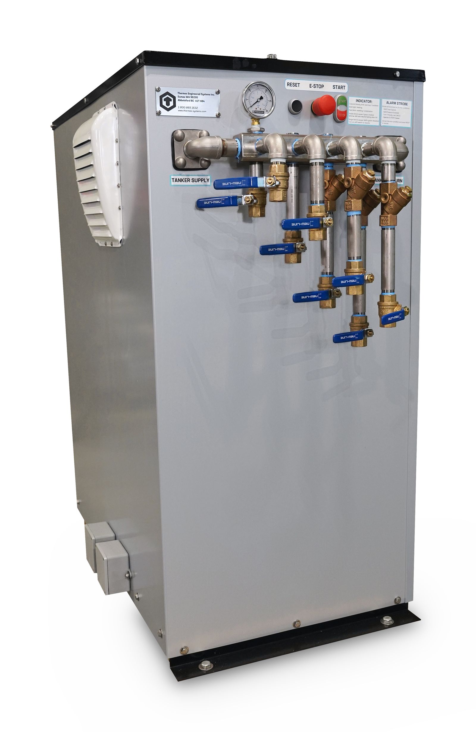
Overview
The TankerTherm Bulk Tank Heating System is a recirculating glycol heating system capable of filling up to four tanker heating jackets in succession, then heating them simultaneously.
The system centrifugal pump is supplied with a positive head of flooded suction from the internal glycol storage tank, which is vented to atmosphere. The pump provides 20 GPM of glycol flow through the electric boiler and out the distribution manifold at pressures ranging from 5 to 20 PSI depending on the number of connected tanker heating jackets and their accompanying piping resistance.
Under deadhead conditions at the distribution manifold, the pump continues to circulate at 20 PSI through a bypass orifice which returns to the atmospheric storage tank. A 30 PSI pressure relief valve is installed at the boiler, protecting the system from any excess pressure condition.
Glycol storage and refill
The internal 10-gallon storage tank is drawn down by 3 to 5 gallons of glycol per connected tanker. When the tank glycol volume drops below the 50% level, a positive displacement refill pump is energized, drawing replacement glycol from the adjacent 55-gallon supply drum and pumping it into the storage tank at 4 GPM.
When tank volume recovers to 95%, the refill pump deactivates. The remaining 5% capacity accommodates system expansion as the heating glycol rises to the 190°F design operating temperature.
The storage tank is vented to atmosphere through a red hose that drains back into the supply drum, so any overflow expansion is entirely recovered.
Major components
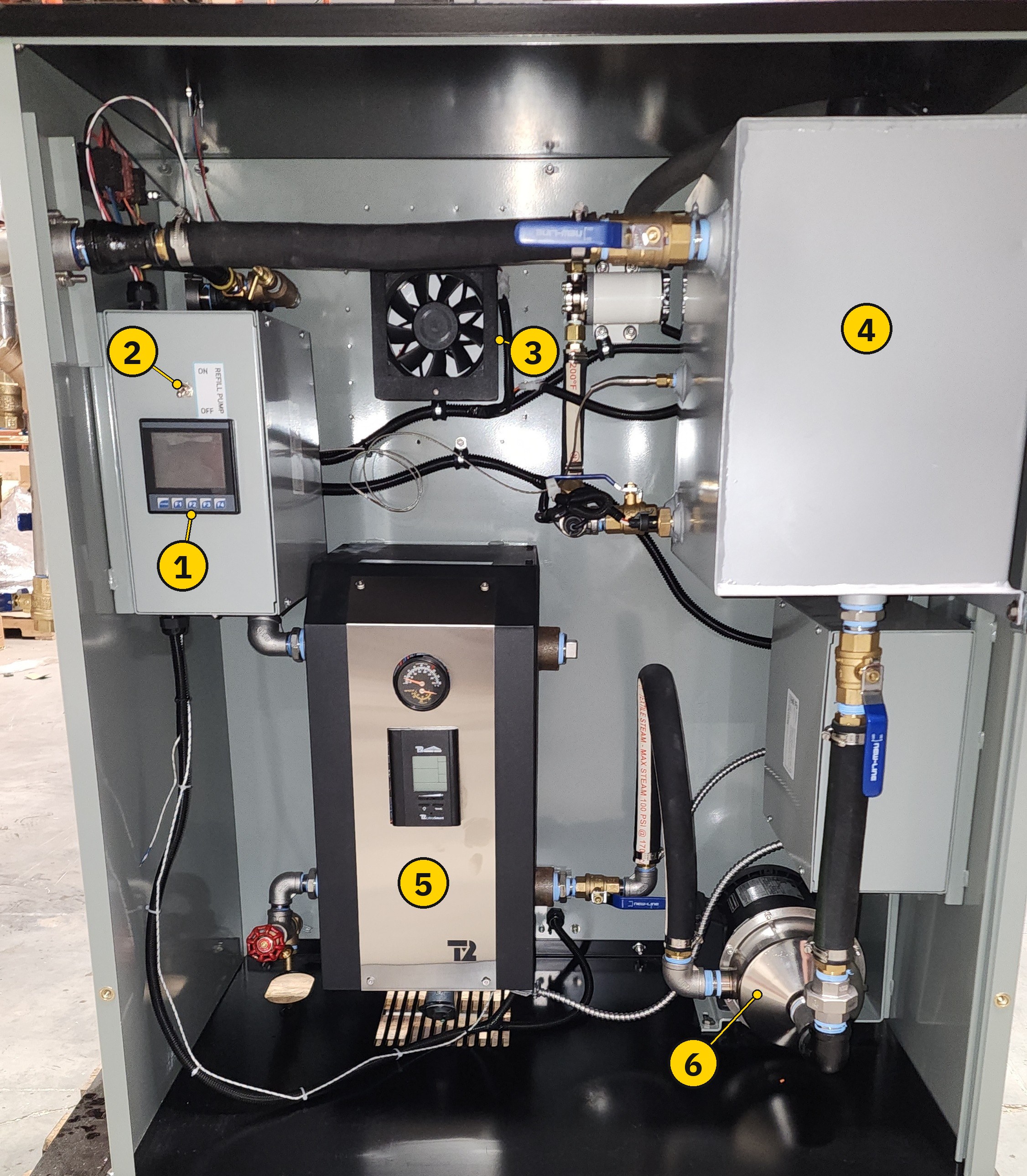
| # | Component | Where it is covered |
|---|---|---|
1 |
PLC touchscreen HMI |
|
2 |
Refill Pump Switch ( |
|
3 |
Cabinet cooling fan |
|
4 |
Storage tank (10 gallons, vented to atmosphere) |
|
5 |
Boiler, with its onboard digital controller |
|
6 |
Circulation pump |
The distribution manifold and the Start, Stop, Reset, and E-Stop controls are on the outside of the cabinet — see Manifold layout. The Remote Output Box is on the rear of the unit — see Remote Output Box.
|
Optional equipment
An auxiliary circulation pump — a third circulating pump that drives a separate heating loop — is available as a special-order option. Most units are built without it, and it is not shown above. See Auxiliary circulation pump. Deprecated: the auxiliary circulation pump is not supported in later PLC software. |
Controls and monitoring
The unit is supervised by an industrial PLC controller with an integrated touchscreen HMI on the inside-left wall of the cabinet. The PLC handles diagnostics, field calibration, and event logging, and drives a 0–10 V analog output of tank temperature for remote monitoring.
Day-to-day operation is via the Start, Stop, and Reset buttons on the manifold control panel — see PLC Controller Overview for PLC-specific functions.
Quick links
The sidebar groups this manual into the following sections:
-
Safety — Hazards, lockout requirements, and how safety notices are used
-
Specifications — Complete technical data
-
Installation — Unpacking, power connections, initial system fill, and the Remote Output Box
-
Operation — Startup, connecting tankers, temperature control, and the refill system
-
PLC Controller — Status, calibration, controls, output tests
-
Maintenance — Scheduled and as-required maintenance
-
Troubleshooting — Common issues and resolution
-
Warranty — Terms and claim procedure
-
Release Notes — What changed in each revision of this manual
|
Before you begin
Read the Safety page and the entire Installation section before unpacking or energizing the unit. Improper startup procedures — particularly skipping the air-purge step — can damage the boiler. |