Power Supply Connections
The TankerTherm 123 ships in two voltage variants. The connection procedure is identical; only the supply voltage differs. Confirm your unit’s SKU on the unit nameplate before energizing.
| SKU | Supply | Connection block label |
|---|---|---|
|
480 VAC 3-phase, 36 kW |
|
|
600 VAC 3-phase, 36 kW |
|
|
Qualified electrician required
All electrical connections must be performed by a licensed electrician in compliance with local electrical codes. Disconnect and lock out the power source before beginning any electrical work. |
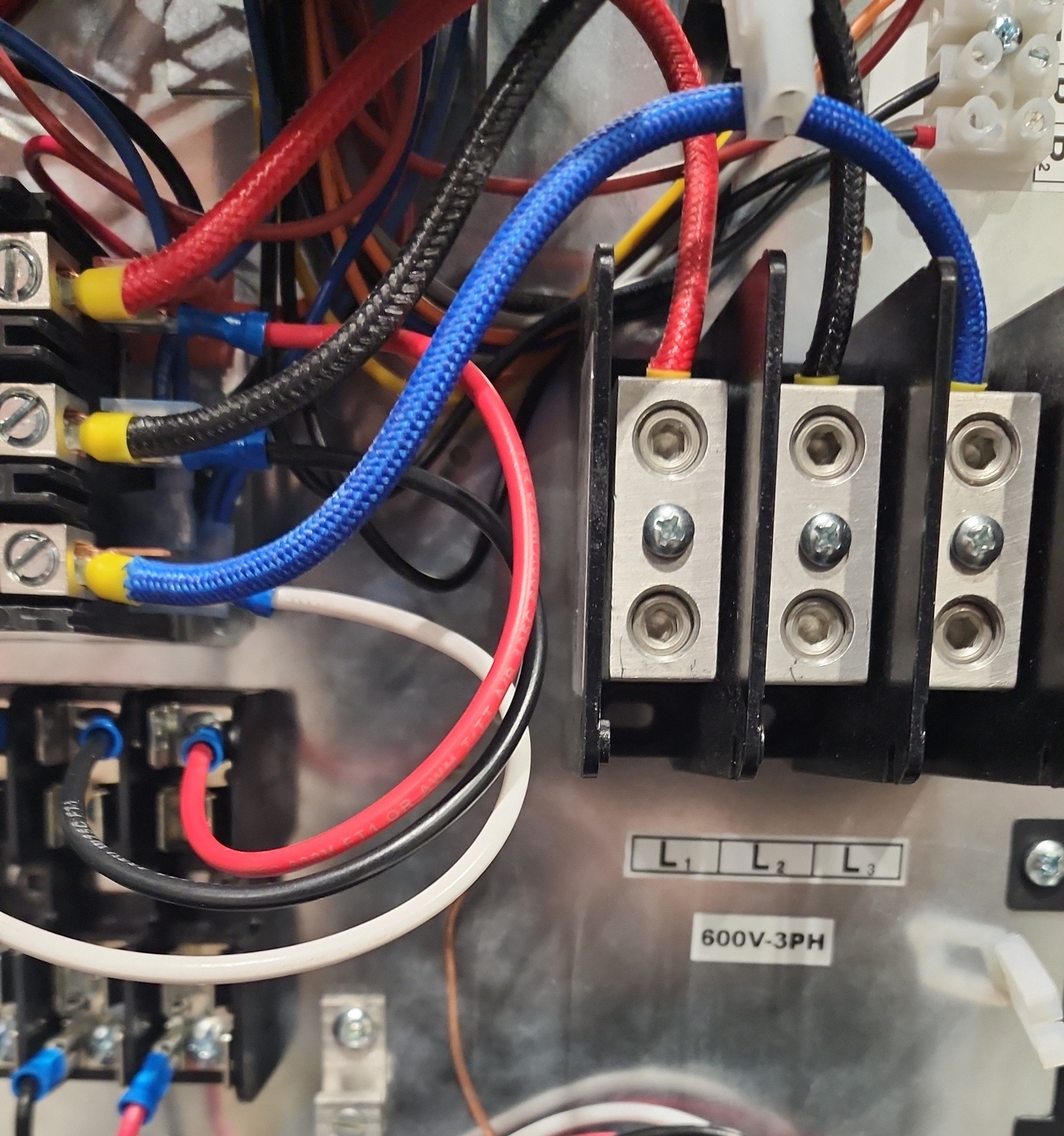
L1, L2, L3 lugs labelled 600V-3PHConnection procedure
-
De-energize and lock out the supply.
-
Open the upstream main disconnect that will feed the unit.
-
Lock out and tag out the disconnect per site procedure.
-
Verify zero voltage on the supply conductors with a properly rated meter.
-
-
Remove the boiler cover and set it aside — it is reinstalled after initial startup is completed.
-
Route electrical cabling in through the 4×4 pull box on the rear of the cabinet.
-
Run cables through the attached conduit into the boiler.
-
Connect the 3-phase wiring — at the supply voltage matching your SKU (480 V or 600 V) — to the labelled connection block.
-
Connect the grounding conductor to the grounding lug.
|
Leave the boiler cover off until after the air purge
The boiler cover must remain off until after the air-purge procedure described in Startup & First Heat Cycle. Installing the cover prematurely prevents access to the boiler control wire that must be temporarily disconnected during the air purge. Once the supply is connected, the boiler face is live whenever the main disconnect is closed. Before touching the boiler control wire or any other wire at the boiler face, open the main disconnect, lock it out and tag it out, and verify zero voltage — see Startup — Step 1. |
Verify before energizing
Before applying power, verify:
-
The unit’s SKU and nameplate voltage match the supply voltage
-
All three phases land on the labelled connection block (
480V-3PHor600V-3PH) -
Grounding lug is secured with a properly sized conductor
-
No loose conductors or debris inside the boiler
-
Boiler cover is off (to be reinstalled after air purge)
-
Conduit entries are sealed against weather
Next step
Proceed to Initial System Fill to fill the glycol storage tank before the first startup.