Connecting Tankers
The TankerTherm 123 supports up to four tankers connected at once. Connect and fill them one at a time, in succession; once filled, all connected tankers are heated together. Any tanker can be disconnected individually without interrupting heating of the others still connected.
|
Hot surfaces — personal protective equipment required
The distribution manifold and piping operate at up to 190°F (88°C). Always wear heat-resistant gloves when engaging ball valves or connecting/disconnecting tanker lines. Direct contact with the manifold can cause severe burns. |
Manifold layout
The distribution manifold is divided into a supply side and a return side. Each side is labelled on the panel:
| Panel label | Position and components | Purpose |
|---|---|---|
|
Left side — pressure gauge, ball valves |
Hot glycol supply to tanker(s) |
|
Right side — wye strainers, ball valves |
Return connection from tanker(s) |
This manual calls them the supply side and the return side.
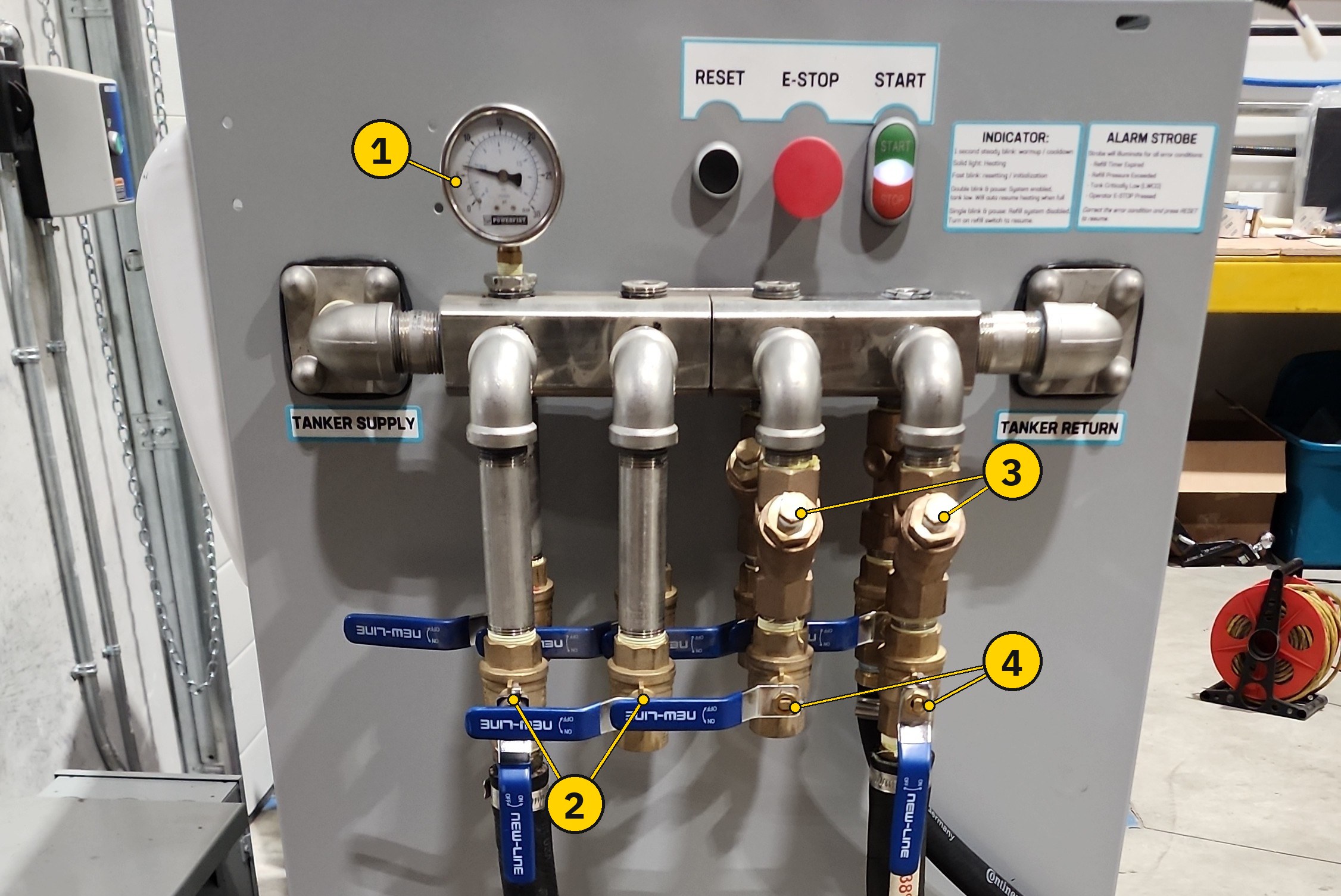
| # | Item | Notes |
|---|---|---|
1 |
Pressure gauge |
Supply pressure at the manifold. See Reading the pressure gauge. |
2 |
Supply-side ball valves |
One per tanker supply line, on the |
3 |
Wye strainers |
One per return line, on the |
4 |
Return-side ball valves |
One per tanker return line, directly below its wye strainer. Return glycol passes through the valve, then the strainer, into the manifold. |
The panel also carries labelled RESET, E-STOP, and START / STOP buttons, and the printed INDICATOR and ALARM STROBE legends — see Manifold panel indicators and Emergency stop.
|
Reading a ball valve
The manifold uses quarter-turn ball valves. The handle shows the valve position: parallel to the pipe = open, perpendicular to the pipe = closed. |
Connection procedure
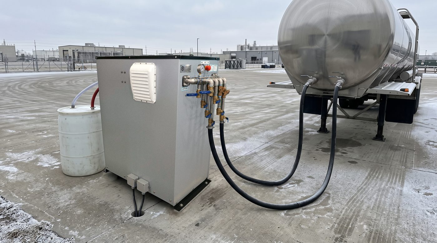
-
Put on heat-resistant gloves.
-
Confirm the system is running and at operating temperature. Quick check: the boiler digital controller reads near 190 °F, and the PLC home-screen banner reads
Enabled-Heatingwith Circ and Heat indicators solid. -
Verify that the supply-side and return-side ball valves you will use are
CLOSED. -
Connect the tanker supply line to a ball valve on the supply side (
TANKER SUPPLY, left, with the pressure gauge). -
Connect the tanker return line to a ball valve on the return side (
TANKER RETURN, right, through the wye strainer). -
Slowly open the return-side ball valve first.
-
Slowly open the supply-side ball valve.
-
Verify flow on the pressure gauge — pressure should settle within the 5–20 PSI range depending on connected load.
Each manifold ball valve ends in a standard hose barb. Push the hose fully onto the barb and secure it with a worm-drive hose clamp. No special fittings are needed.
To connect more tankers, up to four in total, repeat steps 3–8 for each tanker, one tanker at a time.
Reading the pressure gauge
The gauge shows supply pressure at the manifold. With no tanker circuits open, the pump circulates through the internal bypass orifice at 20 PSI. As tanker circuits are opened, glycol flows through the jackets and the reading falls. The normal range is 5–20 PSI, depending on the number of connected jackets and their piping resistance.
If pressure fails to exceed 7 PSI with no tankers connected, the circulation pump is worn — see Troubleshooting — Pressure fails to exceed 7 PSI during bypass.
Disconnecting a tanker
An individual tanker may be disconnected while the system continues to run for other connected tankers.
|
Hot surfaces — personal protective equipment required
The distribution manifold and piping operate at up to 190°F (88°C). Always wear heat-resistant gloves when engaging ball valves or connecting/disconnecting tanker lines. Direct contact with the manifold can cause severe burns. |
-
Close the supply-side ball valve for the tanker being disconnected.
-
Close the return-side ball valve.
-
Allow the tanker lines to cool, or use heat-resistant gloves to disconnect immediately.
-
Disconnect the supply and return lines from the manifold.
To disconnect several tankers, repeat these steps for each one. When the last tanker is disconnected, shut the system down as described below.
Shutdown (all tankers disconnected)
If all tankers have been disconnected:
-
Press the Stop button to end the heating operation.
-
The control system remains in standby mode.
-
Standby mode continues to monitor:
-
Glycol level
-
Temperature controls
-
Enclosure temperature
-
No further action is required until the next heating operation is initiated.