PLC Calibration
The Calibration menu provides three calibration routines: tank level, temperature probes, and refill pressure.
|
PLC navigation at a glance
|
|
Calibration overwrites the stored sensor scaling
Calibration changes the constants the PLC uses to interpret raw sensor signals. An incorrect calibration makes the PLC misread tank level, temperature, or refill pressure, and its protection logic acts on those readings. Perform these procedures only when commissioning the unit, after replacing a sensor, or when verifying readings against a known reference. The Calibration menu requires the standard password ( |
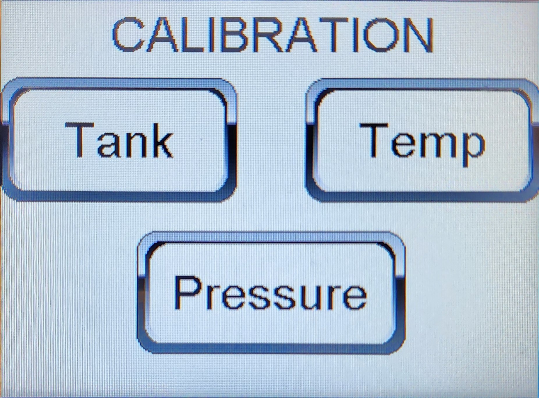
Tank level calibration
The storage tank level is measured by an analog sensor and reported as a percentage on the home and Status screens. Two calibration points define the percentage scale: the empty point and the full point.
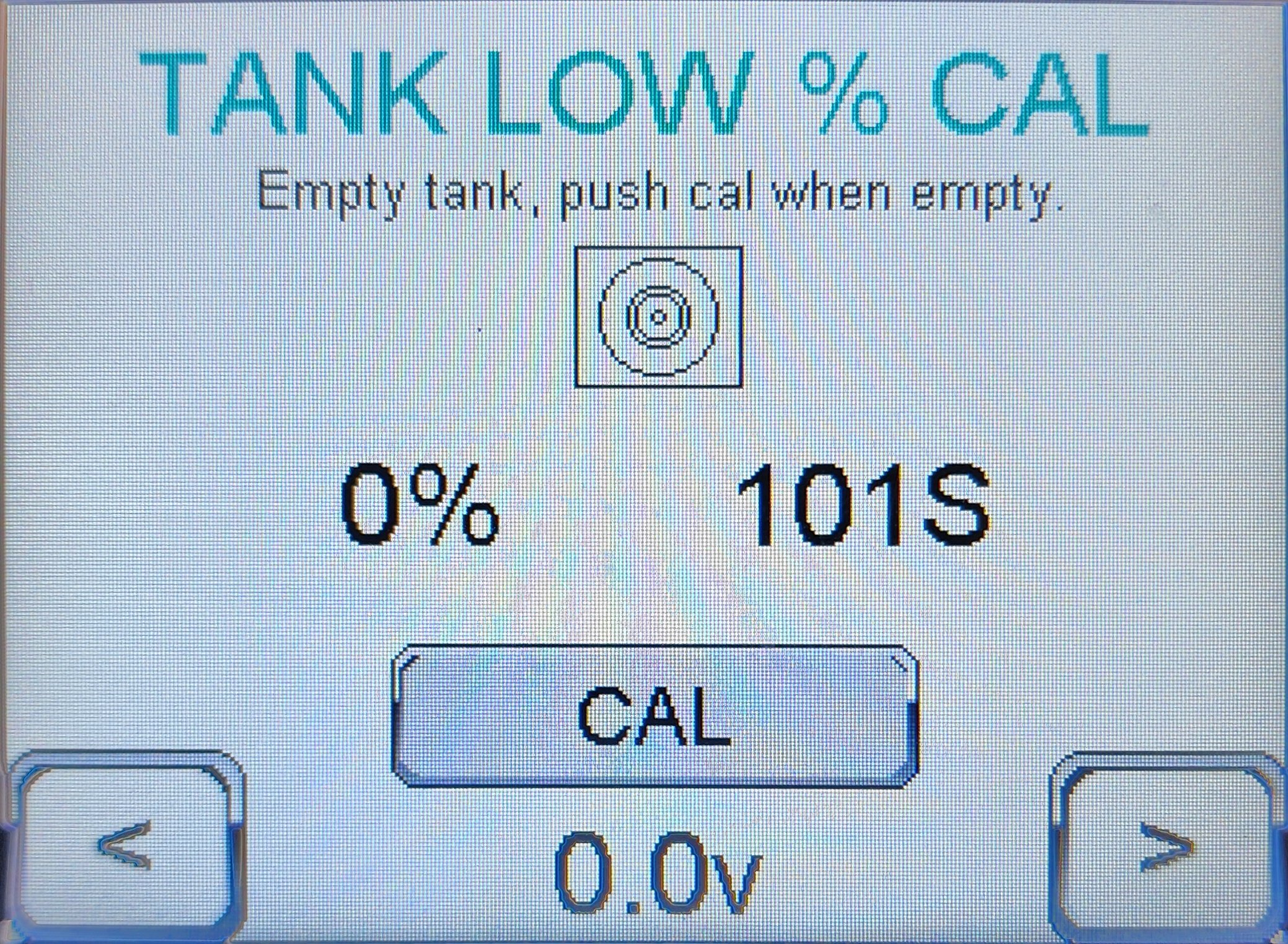
Tank Low % (empty) calibration
|
LWCO interlock
The empty-tank calibration requires the LWCO sensor to be in the Low state — i.e. the tank is actually empty. This prevents accidentally calibrating the empty point when there is still coolant in the tank. |
-
Drain the storage tank completely so that LWCO trips. Confirm LWCO: Low on the Status screen.
-
Press F2 from the home screen, enter the password, and select Calibration → Tank → TANK LOW % CAL.
-
Confirm the on-screen voltage reading is stable at the empty-tank reference (typically near 0.0 V).
-
Press CAL to set the empty-tank zero point.
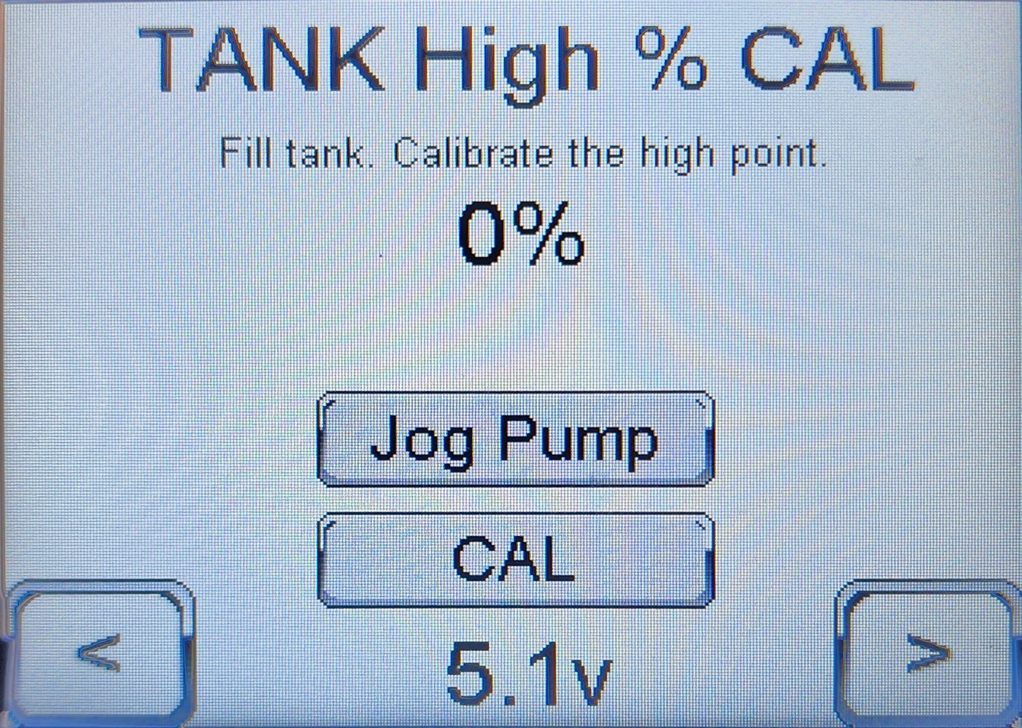
Tank High % (full) calibration
|
Confirming a full tank
The storage tank is enclosed in the cabinet and has no sight gauge. A full tank is confirmed when coolant begins to flow from the tank’s overflow fitting. This procedure uses that point as the full-tank reference. |
-
Confirm the supply drum is full and connected to the suction tube/hose.
-
Press F2 from the home screen, enter the password, and select Calibration → Tank → TANK High % CAL.
-
Press Jog Pump to advance the refill pump in short bursts.
-
Continue jogging until coolant flows from the tank’s overflow fitting — that is the physical "full" reference.
-
Stop jogging. Confirm the on-screen voltage reading is stable (typically around 5.1 V on a properly-functioning sensor).
-
Press CAL to set the full-tank reference.
-
Verify the result: return to the Status screen and confirm Tank Level reads near 100 %.
-
During the next normal operating cycle, confirm the percentage drops as tankers draw down the tank, and recovers as the refill pump tops it up.
Temperature probe calibration
|
Generally not needed
Factory calibration of the temperature probes is normally adequate for the unit’s service life. Calibrate only if a probe reading is clearly inconsistent with a known reference, or after replacing a probe. |
The PLC reads three thermistor/probe inputs:
-
Tank Temp — coolant temperature in the storage tank
-
Ambient Temp — cabinet ambient temperature (drives cooling-fan and LCD-screen-heater logic)
-
LCD Temp — temperature at the HMI itself (used to manage the screen heater in cold weather)
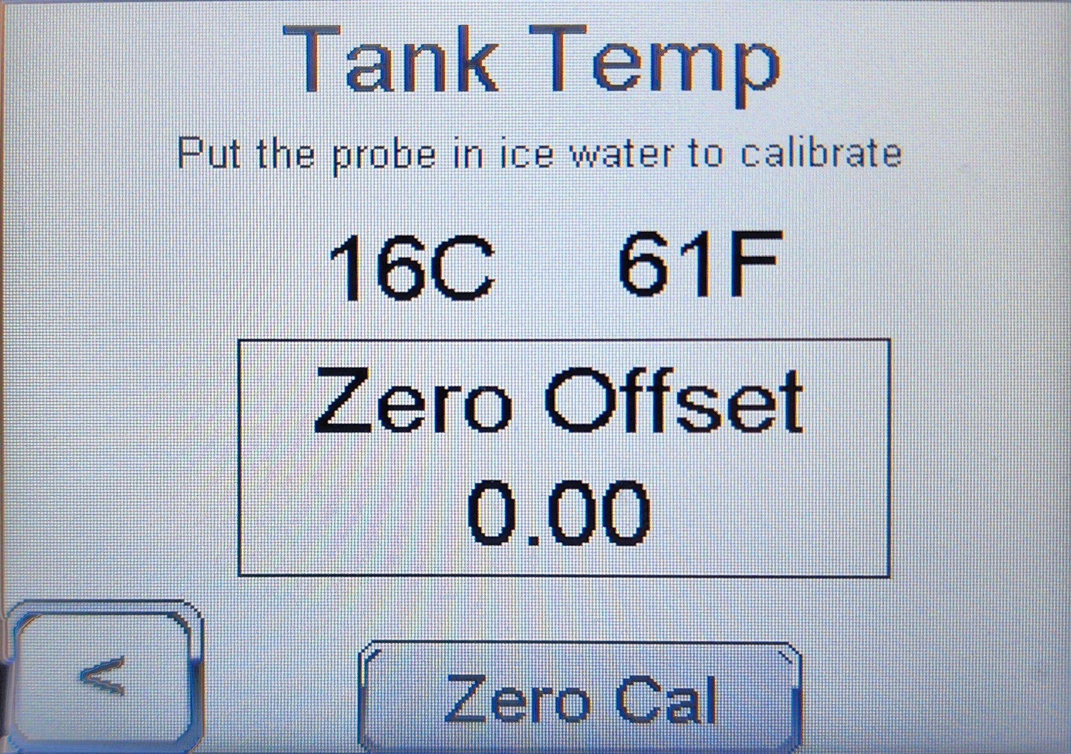
All three calibrate the same way. Each has a single Zero Cal offset, which corrects the displayed reading so that it matches a known reference temperature — an ice-water slurry at 0 °C / 32 °F.
|
Tank Temp probe — drain the tank to ≤20 % before removing the probe
The Tank Temp probe sits in a compression fitting on the storage tank. To place it in an ice-water slurry you must withdraw it from the fitting — if tank level is above approximately 20 %, coolant will flow out the sensor hole. Before calibrating the Tank Temp probe, stop the system and let the coolant cool. Draw the tank down (or drain it) to ≤20 % and confirm the level on the Expanded Status screen before loosening the compression fitting. |
Procedure (all three probes)
-
Place the probe being calibrated into a slurry of crushed ice and water and allow it to stabilize for at least 5 minutes.
-
Press F2 from the home screen, enter the password, and select Calibration → Temp — then choose the probe.
-
Confirm the displayed temperature is stable.
-
Press Zero Cal to apply an offset that drives the displayed temperature to 0 °C / 32 °F.
|
Tank Temp shows both °C and °F; ambient and LCD show °C only
The tank temperature display includes a Fahrenheit conversion since the rest of the manual specifies tank set-points in °F. Ambient and LCD readings remain in °C as they are used internally by the controller for fan and heater logic. |
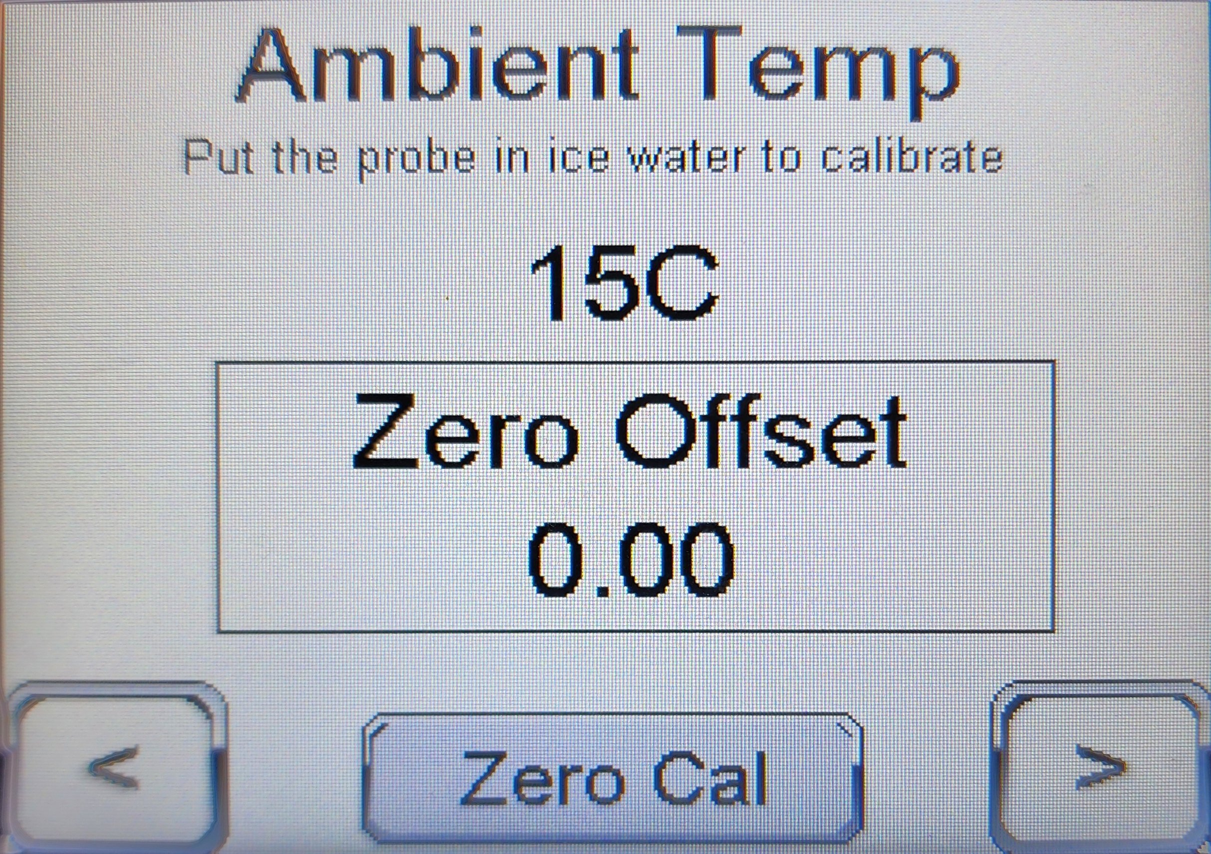
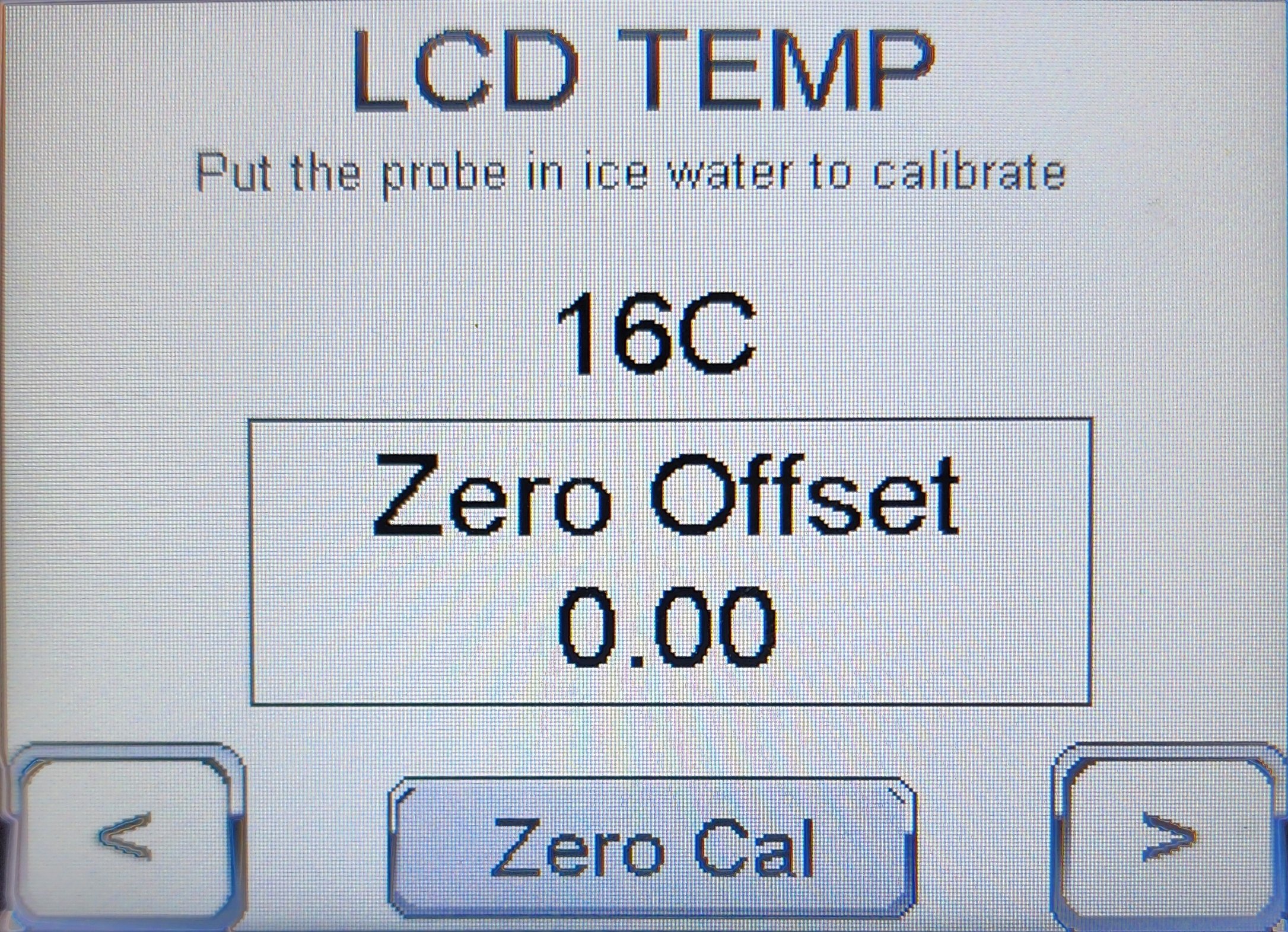
Refill pressure calibration
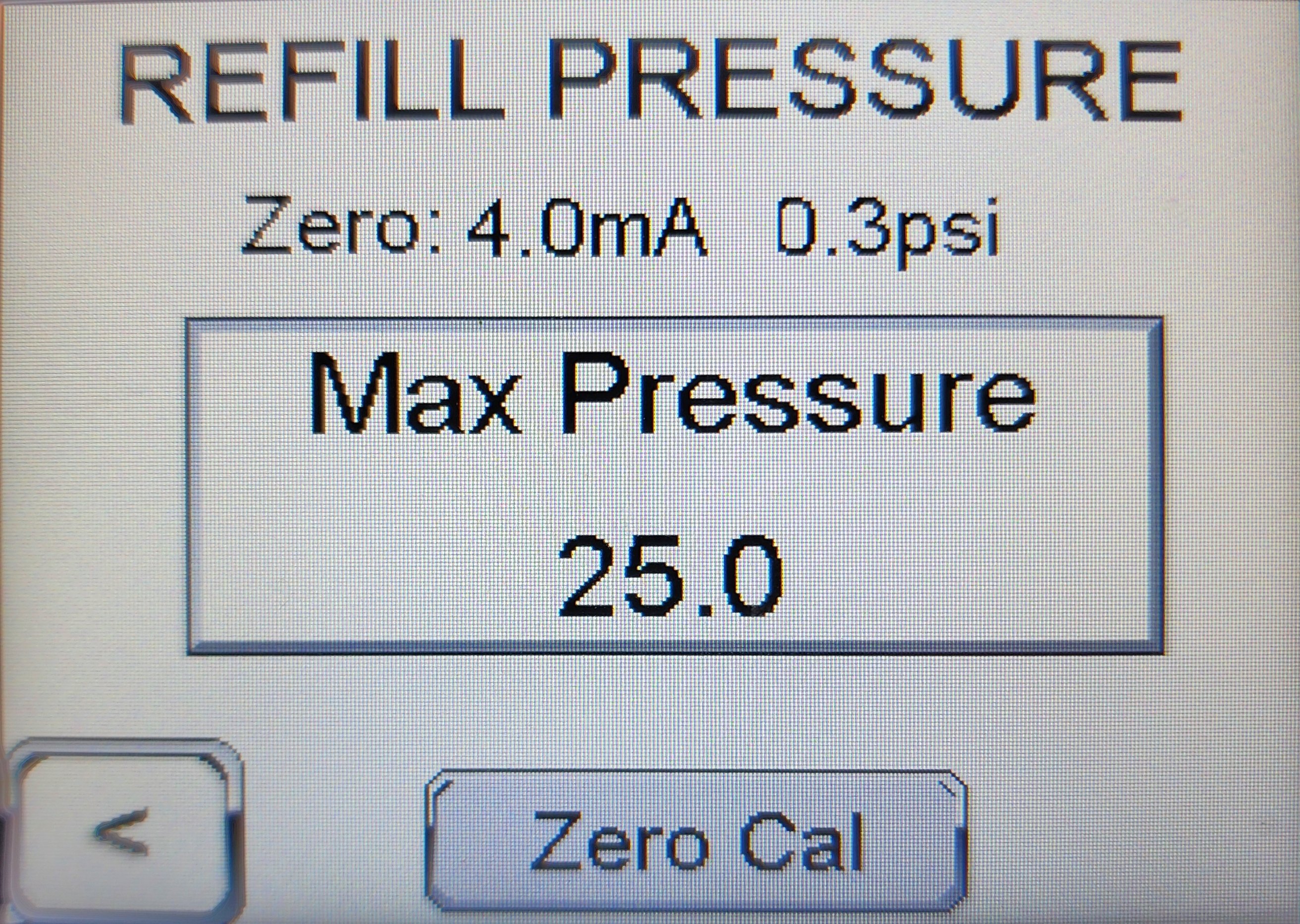
The refill line is monitored by a 4–20 mA pressure transducer scaled 0–30 PSI. Two parameters are accessible from the REFILL PRESSURE screen: a zero calibration and a maximum-pressure cutoff.
Zero calibration
-
Vent the refill line so that the transducer sees atmospheric pressure (no head from the supply drum).
-
Press F2 from the home screen, enter the password, and select Calibration → Pressure.
-
Confirm the displayed reading is near 4.0 mA / 0 PSI.
-
Press Zero Cal to apply the offset.
Maximum pressure cutoff
The Max Pressure parameter (default 20.0 PSI) is the threshold above which the PLC stops the refill pump and latches a Refill Pressure Too High fault. This protects the storage tank and refill plumbing from over-pressurization caused by, for example, a kinked overflow or a closed downstream valve during refill.
|
Do not raise the cutoff toward 30 PSI
The boiler is protected at 30 PSI by the relief valve. Raising the refill pressure cutoff close to or above 30 PSI defeats the protective intent of this parameter, and an over-pressurized storage tank or refill line can rupture and release hot glycol. The factory setting of 20.0 PSI leaves a margin below the relief valve and should not be raised without engineering review. |
To change the cutoff:
-
Press F2 from the home screen, enter the password, and select Calibration → Pressure.
-
Tap the Max Pressure value to open the on-screen number pad.
-
Enter the new cutoff in PSI and confirm.
-
Check that the Max Pressure field shows the new value.
See also
-
Status screen — confirm calibrated readings
-
Fill Time Limit — companion protection to refill pressure